
Hey, you looking’ at ME??
I had learned a lot designing and building my Composite H-Quad, but it ultimately left me dissatisfied for several reasons (beyond my usual perfectionist streak). My chief gripe was that it didn’t transport nearly as well as I had envisioned. Sure, it would disassemble just fine into three major pieces. But you see….I sorta forgot about the props when I was doing my design. Unless I went to the trouble of removing the props from the motors (a pain in the ass for several reasons) they extended the length of each arm assembly by ten friggin’ inches!
And the props were, well, bendy. On my first effort to field test the quad I packed it in 4 miles in a large daypack. When I pulled it all out for assembly, I found the top and bottom of the pack had bent the damn props that were sticking out. It flew, but it let me know it wasn’t happy about it with copious amounts of Jello on the video I recorded. Interesting lesson learned.
The other growing problem with the quad was that I had beat the crap out of it while learning (somewhat) to fly. It took some amazing high speed crashes into the ground and survived. Mostly. There were growing cracks in the balsa portions of the fuselage and my repair efforts were marginal. There was only so much that could be done and it looked like it was time for the patient to get its affairs in order.
But the kiss of death was the new Arducopter software, version 3.0, that had come out for my APM flight controller. It greatly increased the reliance on the internal sensors, especially the magnetometer (the compass) and the accelerometers. If these items were addressed, the thing could fly amazingly and hold a solid position on its own in high wind. But if the vibration was too high for the accelerometers or magnetic interference was generated by the wiring, the craft could fly away in some random direction or toilet bowl into the ground. The latter is actually a recognized multicopter flying term. You don’t want it to happen. It’s expensive.
In testing, I found my battery wiring was generating a magnetic field equal to over 70% of the Earth’s magnetic field….but in the wrong direction. Toilet bowl time. The only way to rectify that would be to rearrange the power wiring. But in an amazing flash of foresight when I had assembled my quad, I installed all its power wiring into the fuselage then epoxied the damn thing shut. So it was not fixable. Time for a rebuild. And what I find really appealing about this “hobby” (or whatever you want to call this money pit) is that at this point in its evolution if you want something even slightly unconventional you have to build it yourself.
I had seen a few folding quad designs where the arms folded in against the sides of the body and the props sort of “nested” there. I thought this concept provided a high measure of protection and would avoid “kinky prop syndrome”. I was also looking for considerably longer flight times than the 9 to 10 minutes I had been getting, so that meant slower turning motors and larger props. And all the wiring had to be kept well away from the flight controller, and oh while you’re at it, minimize vibrations to the flight controller too. How hard could it be?
I liked the general result I had previously achieved using a composite of G-10 fiberglass sheeting and wood, and this time I chose to use Basswood. Much stronger than Balsa but still very light. So I decided to use similar construction techniques. The arms were mainly composed of 10 mm square Basswood to take compressive loads and skinned with a thin G-10 fiberglass layer on the tops and bottoms to take the tension. This engineering stuff is good for something after all.

This shows the arm construction sequence. Top are the individual Basswood pieces. Center are the G-10 skins. Bottom is an assembled arm.
Setting the arm length was challenging and required a lot of CAD time. To nest, the props needed to be shorter than the fuselage but they also needed to fold outward to the right, balanced locations. Throw into this mix the need to pick the right motors matched to the right props to lift an aircraft weight I hadn’t fully worked out. I think I had one more variable than equations. Doing a lot of analysis, I was eventually able to freeze a design that looked appealing.
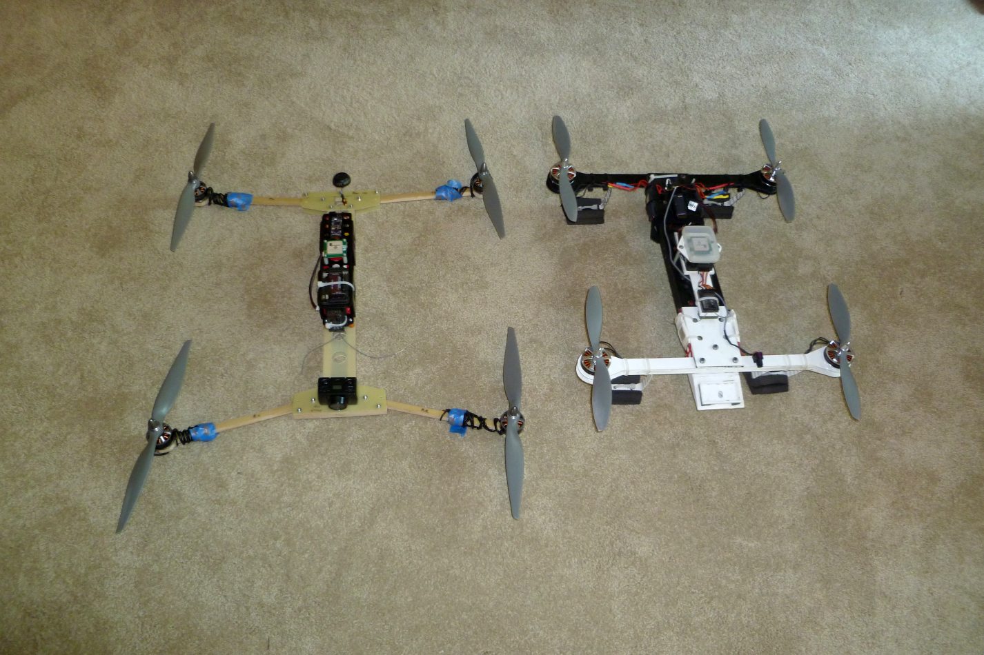
A size comparison during the Folder’s early construction between it and my previous Composite H-Quad.
The body had a similar design to the arms, with Basswood compression spacers and G-10 top and bottom plates. The wiring was bundled tightly together to minimize the magnetic field generated but also designed to be removable. See, I can learn.
The folding mechanism merely pivots the arms on aluminum 4-40 screws, with adjacent screws that tighten to lock the arm in place. All the nuts are Nylock types to prevent loosening from vibration.
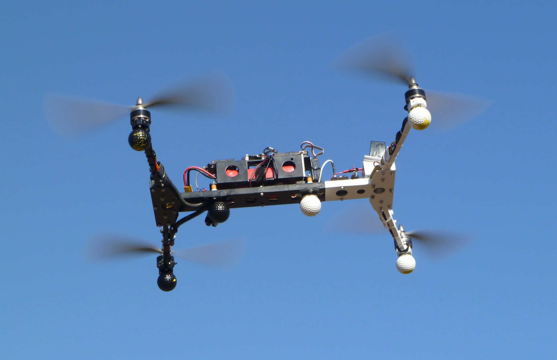
A side view of the Folder in flight. The “golf balls” are actually foam Nerf balls which act as temporary energy absorbing landing gear during testing. They are easily removable and aren’t necessary if one flies reasonably. I must try that some time.
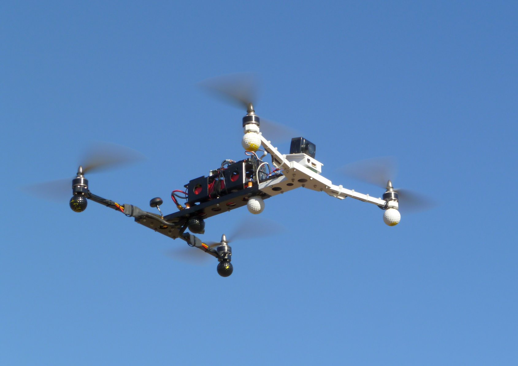
Another view of the Folder in flight. The small forward FPV camera is visible below and to the left of the HD recording camera. The 5.8 GHz circularly polarized antenna is the black mushroom at the rear.

The Folder in its folded position, ready for transport.

The underside of the Folder in the folded position. The downward looking FPV camera is visible in the upper lightening hole in the white area.
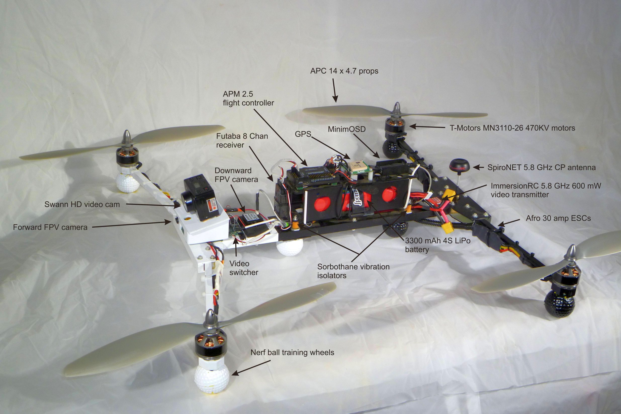
To get the power wiring away from the magnetic compass I mounted the flight controller high on a box containing the battery. This box superstructure also contained other electronics like the GPS, RC receiver and onscreen display board. The box was constructed of 2.5 mm plywood (to help kill vibrations) and connected to the fuselage via four Sorbothane vibration isolation mounts. The large mass of the box, combined with the Sorbothane isolation worked fantastically to reduce vibrations to the flight controller (which was further isolated on its own special elastomer gel mounts). The compass interference was reduced from my previous 70%+ to about 6%. That’s outstanding.
Camera placement was an issue I went back and forth on. I wanted to be able to carry an HD video camera or one of two high-pixel still cameras either pointing forward or downward for mapping. And I needed room for a decent FPV camera. Given the narrow fuselage and the odds that I’ll occasionally land hard, nothing of any importance (like expensive video cams!!) can be mounted underneath.
So of course I ended up with two FPV cameras. A very small one, facing forward tucked under the main camera mount as the primary flight camera. The second one looks straight down through the fuselage. They feed through a video switcher which I can control from my RC transmitter. This allows me to look either straight ahead for normal flight, or straight down to verify position for mapping or other important imaging. That downward looking camera is also relocatable to the rear of the fuselage should I have need for a “back up camera”. And I can think of some situations that could prove handy.
Folding Composite H-Quad parts layout
So at this point I’ve spent well over a month wringing it out through a series of flight testing and tuning. I’m really pleased. It performs well and flies long. I’ve had a few semi-crashes in its very initial flights and it survived them surprisingly well. The only negative I have to say about it is it’s somewhat feral, with tendencies to attack if one isn’t paying attention.

When drones attack: A large, powerful quad + a moment’s inattention during the tuning process = seven sutures. I’m a bit concerned now that it’s tasted human blood.
Final specs:
- All Up Weight (3.3 Amp hour battery and HD camera): 1,823 grams (4.02 pounds)
- Motor to motor dimension: 736 mm (29″)
- Fuselage length: 470 mm (18.5″)
- Current at hover: 12.5 Amps
- Measured hover time at full weight, to 3.6 volts per cell: 14+ minutes
So it’s ready for the field…..I just need to wrap up the other two drone projects in the pipeline.